Second Order Series RLC Circuit Step Response
Overview
Model and test series RLC second order circuits.
Part 1 - analyze step response of given circuit.
Part 2 - Redesign circuit so its critically damped without affecting natural frequency.
PART1 UNDER Damped Series RLC Circuit:
Pre-Lab
a) Write out differential equation relating V(out) and V(in).
b) Estimate natural frequency, damping ratio, DC gain, period of oscillation
a)
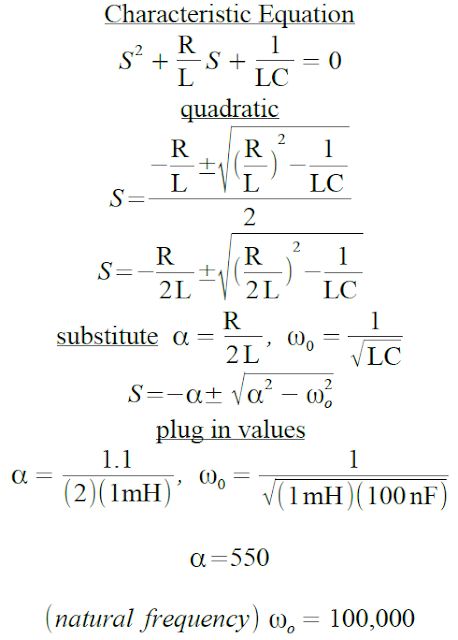
b) Natural frequency
Damping Ratio
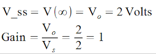
DC gain
 |
at T = INFINITY (STEADY STATE) |
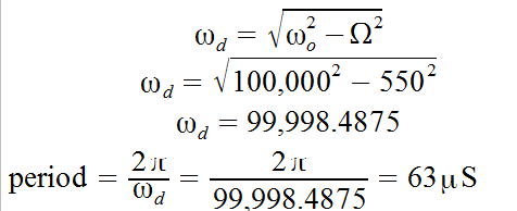
Period of oscillation
LAB
Construct circuit using 2 volt step input and a low frequency so that the circuit can reach a steady state before each pulse.
Results
We can see from the V(out) Oscilloscope on the top right of the figure below that the RLC circuit is UNDERDAMPED as predicted in the prelab. The oscilloscope on the left is V(in) of the 2v square wave, and the right shows the oscillations of V(out).
 |
| Underdamped 2nd order RLC circuit using TINKERCAD |
 |
| Underdamped RLC series circuit using EveryCircuit |
ANIMATION of Underdamped RLC circuit using EVERYCIRCUIT.
PART 2 CRITICALLY Damped Series RLC Circuit:
Prelab
Redesign circuit so its critically damped without affecting natural frequency.
Changing the resistor from 1.1 to 200 should make circuit critically damped.
LAB
Modify Circuit from Part 1 to create critically damped circuit without affecting natural frequency.
Results
RLC circuit is critically damped with resistor changed to 200 ohm's. Since L, and C are unchanged, natural frequency remains the same as in part 1.
The image below shows the circuit on a breadboard similar to Part 1, where the only change is the resistor from 1.1 to 200 ohms which gives a reading of critically damped as expected from prelab of Part 2 where there is no oscillations in V(out).
The image below shows the circuit on a breadboard similar to Part 1, where the only change is the resistor from 1.1 to 200 ohms which gives a reading of critically damped as expected from prelab of Part 2 where there is no oscillations in V(out).
|
|
| Critically Damped RLC circuit using TinkerCad App
We can see with the figure below, that V(in) is represented in orange and V(out) is represented in green, which shows no oscillations which is critically damped compared to Part 1 that was underdamped with oscillations.
|
 |
| Critically damped RLC series circuit using EveryCircuit. |
Animation of Critically Damped RLC circuit on EveryCircuit


No comments:
Post a Comment