Active RC Circuit Step Response
Date: 10/17/17
Overview
Gain an understanding of passive versus active first order circuits. Passive circuits are useful in signal conditioning but arn't good at receiving additional loads which would require redesign of the circuit anytime a different load is applied to the circuit.
Active circuits are somewhat immune to different loads because the power supply comes from external sources.
Lab Procedures
1) Construct circuit from circuit diagram above, using resistors of 470 and a capacitor at 1µF.
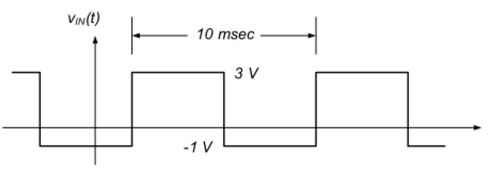
2) Using a function generator, apply 4 volt peak-to-peak square water input with perioes = 10 ms (frequency = 100Hz)
3) Increase frequency to 300Hz, 500Hz, 1,000Hz, and 2,000Hz and comment on behavior.
Results
(100Hz)
 |
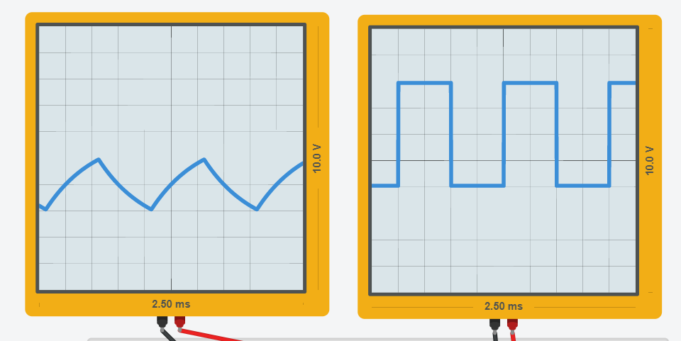
Active RC circuit using op-Amp741 with square wave Voltage input of 100Hz.
The figure below illustrates the capacitor voltage charge vs discharge at 100Hz, resulting in a saw tooth like wave.
adf
(300Hz)
 |
Oscilloscope showing square wave Voltage input of 300Hz
(500Hz)
|
 |
| Oscilloscope showing square wave Voltage input of 500Hz |
|
(1,000Hz)
 |
| Oscilloscope showing square wave Voltage input of 1,000Hz |
|
(2,000Hz)
 |
Oscilloscope showing square wave Voltage input of 2,000Hz
Animation of Ramp of Active RC Circuit Step Response via GIPHY
Troubleshooting
We didn't take photos of our lab because we knew we did it wrong. Our readings on the Oscilloscope where we had one channel for Voltage(in) and one channel for Voltage(out) resulted in the square wave for Voltage(in) which is correct but our Voltage(out) was noisy, with no pattern. We tried troubleshooting over two lab periods where a lab partner constructed his own op-Amp circuit where we got the same incorrect reading for Voltage out. Below was an attempt where voltage out matched Voltage in which is incorrect. I was able to figure out why all of our op-Amps were not giving us the desired outcome when using independent power sources because Vcc(+) and Vcc(-) were not connected correctly. Turns out that we needed two power sources, one for Vcc(+) and one for Vcc(-).
The second figure below was using a resistance load between Voltage (out) and ground giving what we first thought was closer to Ramp but we were incorrect as well.
With incorrect Vcc(+) and Vcc(-), V(out) reading is the same as V(in) which is incorrect, should be Ramp wave.
Adding a resistance load between V(out) and ground, resulted in an usual wave pattern different than V(in), but error resulted because op-Amp was not connected correctly at Vcc(+) and Vcc(-).
|
|
|


No comments:
Post a Comment