INVERTING VOLTAGE AMPLIFIER
Date: 10/3/17
Overview
Gain an understanding of simple single operational amplifier-based circuit that are commonly used in circuits used to implement mathematical operations such as voltage gain within a circuit.
In this lab, we will gain an understanding of a inverting op-Amp circuit diagram and how to complete the circuit using a 8-pin op-Amp and see the relationship between Voltage(in) and Voltage(out).
Voltage (out) is an inverted (due to the sign change) and amplified or scaled (due to the multiplicative factor R2 / R1 version of the input voltage. The scaling factor R2/R1 is called the gain of the amplifier.

The pins for a OP27 op-Amp, or 741 op-Amp, (both single op-Amps), we can see where pins in a circuit are placed on an 8 pin op-Amp. Pins 1,5,8 don't have any connections in this lab. Pin 5 doesn't connect to any part of a circuit, it's simply there to stabilize the op-Amp when placed in a circuit board.


Lab Procedure
Create inverting op-Amp.
Test input voltages from -3V to +4V by step sizes of .5V and record both input and output voltages.
Calculate circuit gain.
Prelab
Calculate Voltage (out) from any by inserting any Voltage. I choose 2 Volts, resistors 22k for R1, and 44k for R2.


Results
 |
| Op-Amp 27 Circuit |
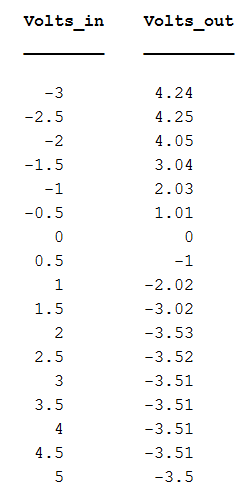
Data and graph of Voltage (in) and Voltage (out) :


Comments
Data is reduced to find the slope of the line from the equation y = mx + b, where m is the slope of the line. The gain in the non -saturated portion of the circuit is -2 as found from the equation of the line.
We can see from our actual Voltage (in) at 2 volts has negative saturation, which is why our Voltage (out) calculated differs from actual. We can see that if we used 1 volt for Voltage in, then the calculated, and actual from data collected would be equal.
Troubleshooting
In our first attempts, in both actual and virtual labs such as TinkerCad App, our attempts never yielded our desirable results. This was the same case using analog discovery.
We used the Vcc (+) and V(-) from same power source which resulted in errors in this lab and other labs that followed. Below is the result of using one power source where positive 5 volts is going into Vcc(+) but negative -5 is not going into Vcc(-) resulting in V(out) being 1.99, nearly the same as V(in). . Originally, I thought I, or we couldn't get our circuit to work because it wasn't connected to ground which in EveryCircuit, simply adding ground made the circuit correct so even adding a ground in the real circuit, it didn't change the result. Only once adding separate V(+) and V(-) into Vcc, was the circuit correct. Below is how the circuit was done correctly and incorrectly.
 |
| V(in) and V(out) for Op-Amp741 which worked out as expected in TINKERCAD APP |
 |
| Correct Op-Amp, neglecting voltage saturation in EVERYCIRCUIT APP |
 |
| Incorrect op-Amp741 circuit in TINKERCAD APP, note, V(out) reads 1.99 volts when it should be -4.00 |
No comments:
Post a Comment