Engineering 44 Fall 2017

Saturday, September 30, 2017

9/28/17 Superposition ||

Superposition ||


Date : 9/28/17

Objective 

          Use super position technique to analyze a circuit. 

 Prelab 

           Calculate voltage at the 6.8k resistor using superposition where from the 5volt source, the 3volt source, and then adding the sum. 

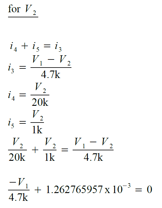
From 5 volt Voltage Source 


Short out 3V, then use Nodal analysis. (red = nodes, blue = current)


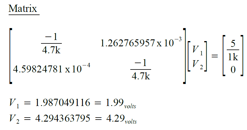
From 3 volt Voltage Source 


Short out 5 volt Voltage Source, use nodal analysis (red = nodes, blue = current)


Lab Procedure 

          1) Construct circuit with both 5volts and 3 volts and record voltage at the 6.8k resistor.


               2) With 5 volt Voltage Source only, record voltage at 6.8k resistor.


               3) With 3 volt Voltage Source only, record voltage at 6.8k resistor.


              4) table

Comments 
            Decided to use resistors 6.8k, 2.2k, and 1k in series to get 10k resistance for the required 10k resistor. Also doubled those values to get to 20k instead of using 22k resistor. The calculated vs actual was spot on. Not sure why we nearly have 0 percent error for both the 5 volt voltage source and the combined voltage source, yet we have a %1.14 error for the 3volt voltage source.  I also realized from the last superposition lab, that I could of simply used any method but I choose to simplify and convert to get toward my answer. 

The TinkerCad app and EveryCircuit App was used to verify with accuracy the values for voltage from each voltage source. 
           
Voltage at 6.8k resistor with both 3v and 5v Voltage Sources


Voltage at 6.8k resistor with 5 volt Voltage Source (3v is shorted
.
Voltage at 6.8k resistor with 3 volt Voltage Source. 

Both Voltage Sources 


3v Voltage Source


5v Voltage Source


Tuesday, September 26, 2017

9/26/17 SuperPosition |


Super Position |

Date 9/26/17

Overview 
            Use circuit reduction techniques in conjunction with superposition to analysis a circuit.  
original circuit 


Pre-Lab 
            Use superposition to calculate V by analyzing V with respect to the 10k resistor from voltage source of 3 volts from the left, and then from the voltage source on the right of 5 volts, and then adding the sums to calculate V. 

Right side 

1) short out Voltage Source of 3 volts
2) Simplify parallel resistors of 20k Ω and 4.7kΩ

    R = (20k x 4.7k) / (20k + 4.7k)
    R = 3805.668016 Ω

3) Simplify series resistors of 3805.7k Ω and 10k Ω

        R = 3805.7 Ω + 10k Ω
        R = 13,805.7 Ω

4) Simplify parallel resistors 

      R = (13,805.7 x 6.8k) / (13,805.67 + 6.8k)
5) Find total current 

          V = IR 
          V/R = Itotal 
          5v / 4556 = Itotal 
          Itotal = 1.0975 x 10^(-3) A = 1.0975 mA

6) Use current divider rule to find current flowing thru 13,805.67k resistors from step 3 figure

    I13805.67 = (1.0975 x 10^(-3)) x ((6.8k) / (13,805.67 + 6.8k) 
    I13805.67 = 3.6217 x 10^(-4) A
    I13805.67 = 362 μA

6b) Find V at 10k 

           V = IR
           V = (362 μA)(10k)
          V = 3.62 volts 


Left Side 


7) Short out 5v voltage source from original circuit 


8) Transform voltage to current, and simplify parallel resisors 20k Ω & 4.7k Ω

           I = V / R
           I = 3 / 20k Ω
           I = 150 μA

             R = (20k x 4.7k) / (20k + 4.7k) 
           R = 3805.67 KΩ


9) Transform current back to voltage and simplify series resistors 

           V = IR
          V = 150 μA x 3805.67K Ω

           R = 10k + 3805.67
           R = 13805.67 Ω


10) Find total current 

           I = V/R
           I = .57085 v / 13,805.67 Ω
          I = 41.3488 μA

11) Find V at 10k 

           V = IR
           V = (41.3488 μA)(10k)
             V = 0.4135 volts 

Combine both voltages at 10k  
        (NOTE: 5v is greater than 3v at 10k resistor so current is flowing west)

       V = 3.62v - .4135v
       V = 3.2065 volts


Or Combine current from both sides at 10k 
      (NOTE: 5v is greater than 3v at 10k resistor so current is flowing west)
   
      362 μA - 41.3488 μA = 320.6512 μA

      V = (320.6512 μA) x (10k Ω) 
      V = 3.2065 volts
      V = 3.21 volts 


Lab Procedure 

1) Build circuit in step 1 of prelab where the 3v voltage source is replaced with a short circuit and record Voltage across 10k resistors. (note: 6.8k, 2.2k and a 1k resistor were used in series to obtain 10k)


2) Build circuit in step 7 of prelab where 5v voltage source is replaced with a short circuit and record voltage across 10k resistors. 


3) Build original circuit and record voltage across 10k resistor. 


Calculated Actual Percentage error
3v removed 3.62 volts 3.61 volts % 0.277
5v removed 0.4135 volts 0.37 volts % 10.8
3v, 5v remain in circuit 3.21 volts 3.22 volts % 0.311


Comments : 

          This lab was tricky to figure out with the short, I realized that I had to keep the short which still had current despite it initially being equal to zero where we were able to then have the resistor next to it also be zero. In the simulation using EveryCircuit, I was able to create a short using a Ammeter which resulted in the same results, with my calculations being more accurate than the app rounding numbers. I also realized that from the left side we could of done mess method which also resulted in the same results where current flows thru the 10k resistor.
         It was odd to have very minimal percentage error of less then 1 percent for removing the 3v voltage source or the combined voltages, but then the spike in increase regarding the percentage error with having the 5v voltage source removed. When connecting open circuit to a DMM, the reading was .35 which would of resulted in a greater percentage error. 

TinkerCadApp

EveryCircuitApp
Super position for left side 

Super Position for right side 


Thursday, September 21, 2017

9/21/17 Nodal Analysis III


Nodal Analysis |||

Date of lab : 9/21/17


Overview 

Testing a circuit containing multiple voltage sources. We will use nodal analysis to predict circuit behavior.
Pre Lab

Use nodal analysis techniques to predict the voltage V1 and current I1


Lab Procedures 

1a) Measure and record all actual resistance
        4.7k (resistor) = 4.4k (actual resistor)
        1.5k (resistor) = 1k    (actual resistor)
        6.8k (resistor) = 6.4k (actual resistor)
        20k  (resistor) = 21k  (actual resistor)

1b) Measure V1 and I1 in circuirt
          V1 (recorded value) = 2.37 volts
V1 = 2.37 volts 


      Percentage error from calculated V1 and recorded V1
           ((2.37-2.31) / (2.31)) * 100 = % 2.6 error

2) Picture of circuit


Comments
            Since we had two given voltage sources next to nodes, then those nodes were equal to those voltage sources such as node V1 = 2 volts and node V2 = 5 volts. Since Voltage travels equally into parallel resistors, we can see that current is entering node V3 and then leaving node V3 toward V2 and ground.
            We can confirm and visually see current flow using the EveryCircuit app below which also shows current at I1.

The TinkerCad app also confirms our calculated value of V1 and I1 and is a visual representation of our circuit for this lab.

Tuesday, September 19, 2017

9/19/17 Nodal Analysis II Multiple Sources

Nodal Analysis II Multiple Sources

Date of lab : 9/19/2017

Overview 
      Use nodal analysis to analyze the circuit.
Pre-lab 

           Use nodal analysis to find Iand V1


Lab Procedure 

V1 = 5.19 volts 


Percentage error between calculated and actual for V1
            ((5.19 - 5.0) / (5.0)) * 100  = % 3.8 error

Comments 
    In nodal analysis, we can observe that node V1 and node V3 are next to voltage sources so node V1 = 5volts and node V3 = 3volts. Since Voltage is the same in parallel resistors, the voltage V1 is the same as the voltage in Node V3 which equals 5 volts. This is simply done by observation without nodal analysis. Since current is entering node V3 from the voltage source, current will be leaving toward I1 and the 6.8k resistor.  So then we simply move to node V2 where current is entering from node V3 and node V1 and leaving at I2. 

We can observe from the Tinkercad App that simulated I1, and V1 is the same as our calculated values. Along with observing current flow from the Every Circuit App. Our error resulted from our voltage source dialed in at 5.2 volts. 

TinkerCadApp
EveryCircuitApp

Thursday, September 14, 2017

9/14/17 Mesh Analysis III

Mesh Analysis |||
Date : 9/14/17

Overview 

Use mesh analysis to analysis a circuit containing multiple sources. Fine I1 and V1

Pre-lab

Calculate I1 and V1. (note : we measured actual resistors and then calculated from new resistor values). 

loop 1: 
           4.4k (i21- i2) + 1k (i1) + 6.4k (i1 - i3)  = 0 

           simplifies to  11.8k (i1) - -4.4k (i2) - 6.4k (i3)  = 0 

loop 2
         4.4k (i2 - i1) + 5 -2 = 0 

        simplifies to    -4.4k (i1) + 4.4 (i2) = -3 

loop 3
         6.4k (i3-i1) + 21k (i3) - 5 = 0 

         simplifies to   -6.4k (i1) + 27.4k (i3) = 5 

matrix of loop1,2,3


I1 =  - 3.1026 x 10^(-4) A = -310 μA

I2 =  -9.9208 x 10^(-4) A =  -992 μA

I3 =  1.1 x 10^(-4) A = 110 μA

V1  (V = IR ) 

       V1 = (110μA) (21,000)
       V1  = 2.31 volts


Lab 

1a) Measure and record all actual resistance
        4.7k (resistor) = 4.4k (actual resistor)
        1.5k (resistor) = 1k    (actual resistor)
        6.8k (resistor) = 6.4k (actual resistor)
        20k  (resistor) = 21k  (actual resistor)

1b) Measure V1 and I1 circuirt
          V1 (recorded value) = 2.37 volts


      Percentage error from calculated V1 and recorded V1
           ((2.37-2.31) / (2.31)) * 100 = % 2.6 error

2) Picture of circuit


Comments : Our calculated value of V of 2.31 volts matches the simulated value in the Every Circuit App, along with our calculated value of I1 = 310 μA. Our negative calculated values of I0 and I1 designates opposite direction of current flow as indicated in the figure in prelab or in the Every Circuit figure above. 

In each lab, we have use calculated values which at times results in everyone getting different answers until we all agree. Sometimes our recorded values is different than expected where we then try to trouble shoot what the issue is which mainly occurs with a loose wire, wrong resistor, wrong voltage source cable location or simply multi-meter error. Using the Tinker Cad app to display a simulated breadboard version helps to visualize our circuit when it is hard to read in the photo and confirm our calculated values. As shown with Tinker Cad, both I1 and V1 are same as our calculated values. 


TinkerCadApp


EveryCircuitApp