Dependent Sources and MOSFETs
Date 8/31/17
Overview
Gain an understanding of transistors by using variable voltage inputs to see how a MOSFETs (Metal Oxide Semiconductor Field Effect Transistors) works. MOSFET'S come in n-channel and p-channel, we will be using a ZVN2210A n-channel MOSFET. The three terminals of the device are called the source (S), the drain (D) and the gate (G).

Lab Procedures:
 |
| Circuit Diagram from Lab Procedure |
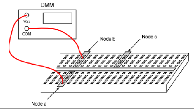
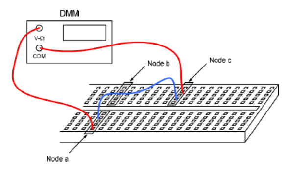
1) Make a circuit as shown in the figure below. Connect variable voltage source and a volt meter to the G terminal of the MOSFET, with the d terminal toward the 100 resistor. and s terminal toward ground node.
2) Starting from 0 volts, apply voltage until there's a current reading in the second Digital Multimeter which is set up in Amps. Record value when current records a value and increase in intervals of 0.3 volts and run intervals up to 5 volts.
3) Plot data
4) Using slope from data, estimate value g.
4) Using slope from data, estimate value g.
RESULTS :
 |
| MOSFET CIRCUIT |
Data table of Data collected
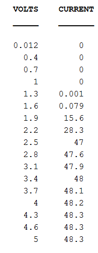

Graph of Data

Slope of data

Value of g = 51(mA/V) based on slope from graph above
This lab we did within our first 2 weeks of class. My group was unsuccessful and I decided to re-due this lab correctly from home. I tried looking for this Mosfet at a electronic store with no luck, and later realized Mosfets are the same as a transistor with the same n-channel and p-channel types. My personal voltmeter gave zeros when I tried redoing this lab and only got 0's for current at all voltage levels, when I realized my Amp meter within my DMM is not working.
This lab, once done correctly was cool to see how transistors require a certain amount of energy to work and caps out within a range specific to each transistor.
